|
|
|
|

Click Photo For Enlargement (79 Kb)
|
|
|
|
Nothing fancy here, a piece of stiff wire connects the actuator to the
trigger. Inexpensive and reliable.
|
|
|
|
|
The paintball feed sits on top of the marker and is held in place
by a steel bracket and a hose clamp. The wire coil flexes as the
gun is elevated, allowing the hopper and feed tube to remain stationary.
|
|
|

Click Photo For Enlargement (351 Kb)
|
|
|
|

Click Photo For Enlargement (100 Kb)
|
|
|
|
The 3rd generation hopper and feed took a bit of trial-and-error to get
everything just right. Here are some of the prototypes that I built.
The three white hoppers were made quickly from aluminium flashing. Easy
to cut and fold, allowing me to get a feel for the sizes and orientations
required. The rectangle wooden plug was then made in order to create
a more durable carbon fiber version of the rectangular hopper. A short
wire coil is used as a feed. Finally, a second round hopper was created
using the wooden plug in the upper left corner. Both the round and the
rectangular hoppers can be mounted on the same bracket in order to
see which works best.
|
|
|
|
|
I've made a number of elevate motors/servos, but this is the best
so far. A strong geared motor and steel arm does the heavy lifting,
while a simple 5K pot and an inexpensive servo kit from Australia
provides the proportional control. Basically, it's just a big
servo. The entire gun assembly (barrel, mantel, and marker) are
counter-balanced so that the motor doesn't have to work that hard.
|
|
|

Click Photo For Enlargement (85 Kb)
|
|
|
|

Click Photo For Enlargement (108 Kb)
|
|
|
|
The complete assembly easily fits within the confines of the turret,
while providing plenty of room between components for working on
everything as needed. (The angle of the photo makes the CO2 bottle
appear to be outside the turret boundaries, but it isn't.)
With the turret top up and out of the way, everything
is easily reached. More importantly, everything can be quickly eye-balled
during a battle to see what might be about to fail.
|
|
|
|
|
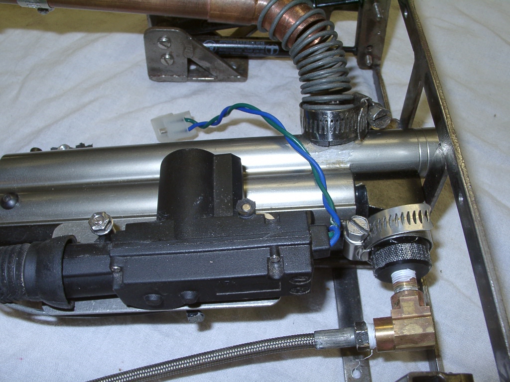
June 2007:
The Tiger turret is ready for battle with a couple of enhancements.
A molded kevlar round hopper serves as the magazine, feeding
the marker through a copper pipe and coiled wire joint (designed
and patented by Will Montgomery). The CO2 bottle is securely mounted in
a metal bracket and manual bypass buttons are mounted to allow easy testing
of the elevate and trigger controls without the gamepad turned on.
|
|
|

Click Photo For Enlargement (94 Kb)
|
|
|
|
|
November 2007:
After years of battling and redesigns of internal systems, the venerable
Tiger T001 is in the shop for an overhaul of the drive system and the
lower hull. Of course, as a national treasure, any work performed on
the Tiger must meet strict guidelines and all materials removed from the
Tiger must be provided to a team of specialists responsible for
preserving them for generations to come.
The current EV Warrior drive system performed well over 4 years of
battling, but it's time to switch to scooter motors to increase
efficiency. After consultations with Dr. Sommer, of the Anvilus
Mechanical Heritage Society, we've decided that the new drive system
should be based on the Anvilus M01 geared motor. That motor provides
plenty of power, good efficiency and a compact layout. The perfect
choice for the 1:6.6 scale Tiger (built to the original 36" rule) which
has little interior room to spare. The space savings provided
by the M01 geared motor should allow the Tiger to carry twice as much
battery power.
Over the years, the lower hull of the Tiger has seen a lot of changes.
Two different track assemblies have been bolted on underneath, three
different track tensioning systems inside, and two different drive
systems have taken their toll on the lower hull. Not to mention the
introduction of a "middle" hull along the way and countless re-mounting
of wires and electronics. With the introduction of the third drive
system and an additional battery, it really is time to refurbish or
replace the lower hull. Keep in mind, the Tiger hull was first
constructed back in early 1990s, a decade before it was ever battled.
Original hull design and construction was based on warship techniques,
which at that time were primarily wood, glue and resin. Not only have I
learned different skills since then, but I've helped design and build at
least a dozen other tanks and vehicles in the last 5 years alone. It's
time to use those lessons to keep the Tiger rolling along. Dr. Sommer
has also offered a water-jet cut aluminum hull as the replacement and
that is being considered by the panel of Tiger experts.
|
|
|
|

Click Photo For Enlargement (151 Kb)
|
|
|
|
All of the parts for the lower hull have been fabricated and are ready
for final assembly.
Joe did a great job cutting the side
panels and bending the bottom panels, leaving me with the simple job of
riveting them together with some 1" angle and 3/16" rivets.
The flanges along the top edge of 3/4" angle
are used to connect the middle hull to the lower hull.
The side "running boards" and bearing mounts are made from 3/4" HDPE which
was purchased as recycled boards from McMaster-Carr. They are waterproof and
will last a long time, let's just hope the paint doesn't rub off too quickly.
Two steel brackets were made to bolt onto the back hull plate to handle the
tensioning system for the rear axle.
|
|
|
|
|
I'm happy to say that my original modular design is now
paying off ... the chassis was removed from the old hull
by loosening six bolts and then bolted to the new hull with just
four bolts (to make the next retrofit even easier).
The welded steel chassis is showing no
problems after a couple years of battling.
No fancy suspension here ... that was ripped out
after the very first test run of the Tiger 1, which has been running on
solid axles since the first very battle. Sure, things get jolted pretty
good inside occasionally, but the spring-mounted electronics don't seem
to care. Maybe my next tank will have some sort of suspension, but the
Tiger just keeps rumbling along.
|
|
|

Click Photo For Enlargement (156 Kb)
|
|
|
|

Click Photo For Enlargement (182 Kb)
|
|
|
|
The middle hull serves as a box inside of box, allowing the upper hull
to be removed quickly, while still preventing paint from getting inside the
hull. By detaching it from the lower hull, it makes it easier to work
on the hull and track system.
|
|
|
|
|
|
|